Energy Technologies in SE Europe
Energy technology is an engineering science whose main purpose is the efficient, safe, environmentally friendly and economically viable extraction, conversion, transportation, storage and use of energy, preventing at the same time side effects on humans, nature and the environment.
After the Second World War huge progress has been achieved in developing the energy technologies used globally, while continuous technological progress has resulted in numerous improvements and higher efficiencies as well as the introduction of new low-carbon technologies.
The aim of the present document is to review the main energy technologies already in use in SE Europe but also identify others suitable for application in the region. Such a review was considered necessary in view of the frequent references made in IENE’s “SE Europe Energy Outlook 2016/2017” on specific technologies.
I) Renewable energy technologies
Renewables can be used for both electricity and heat generation. There is a wide range of renewable energy technologies suitable for implementation in SE Europe for a whole variety of different applications, as summarized in Table 4. Renewable energy can contribute to grid-connected generation but also has a large scope for off-grid applications and can be very suitable for remote and rural applications in developing countries. A brief description of renewable energy technologies used in the SEE region follows.
A. Wind energy
A wind turbine generates power by converting the force of the wind acting on the rotor blades into torque. Figure 1 depicts the components of a wind energy system and Table 1 presents its advantages and disadvantages.
Figure 1: Wind energy system schematic

Source: UNIDO (2009)
Table 1: Strengths and weaknesses of wind energy systems
|
Strengths |
Weaknesses |
|
Technology is relatively simple and robust with lifetimes of over 15 years without major new investment |
Site-specific technology (requires a suitable site) |
|
Automatic operation with low maintenance requirements |
Variable power produced therefore storage/back-up required |
|
No fuel required (no additional costs for fuel nor delivery logistics) |
High capital/initial investment costs can impede development (especially in developing countries) |
|
Environmental impact low compared with conventional energy sources |
Potential market needs to be large enough to support expertise/equipment required for implementation |
|
Mature, well developed, technology in developed countries |
Cranage and transport access problems for installation of larger systems in remote areas |
|
The technology can be adapted for complete or part manufacture (e.g. the tower) in developing countries |
|
Source: UNIDO (2009)
In most cases, wind energy systems are classified in three categories: (a) grid-connected electricity generating, (b) stand-alone electricity generating and (c) mechanical systems.
Several turbine types exist, but the most common configuration not only in SE Europe but also at a global level has become the horizontal axis three bladed turbine, as shown in Figure 1). Modern wind turbines vary in size with two market ranges: small units rated at up to 50-80 kW in capacity, used mainly for rural and stand-alone power systems; and large units, from 150 kW up to 5 MW in capacity, used for large-scale, grid-connected systems (UNIDO, 2009). Lately, wind turbine models in the range of 3.0-3.5 MW have become the mainstay in wind farm applications.
B. Solar energy
Solar energy technologies can be divided into two categories: (a) solar thermal systems and (b) solar photovoltaic systems.
(a) Solar thermal systems
Solar thermal systems use the sun’s power in terms of its thermal or heat energy for heating, drying, evaporation and cooling. Many countries in SE Europe have indigenous products such as solar water heaters, solar grain dryers, etc. These are usually local rather than international products, specific to a country or even to a region. The main solar thermal systems employed in most of SE European countries are analyzed briefly below.
Solar thermal power plants
Solar thermal engines use complex concentrating solar collectors to produce high temperatures. These temperatures are high enough to produce steam through close circuit systems, which can be used to drive steam turbines generating electricity. There is a wide variety of different designs, some use central receivers, where the solar energy is concentrated to a tower, whilst others use parabolic concentrator systems.
Solar water heating
Solar water heating systems (see Figure 2) are mainly used in households but also in hotels, hospitals, schools as well as for light industrial needs. The principle of the system is to heat water, usually in a flat plate collector and store it in a tank until required. Collectors are designed to collect the heat in the most efficient, but cost effective way, usually into a heat transfer fluid, which then transfers its heat to the water in the storage tank. The two main types of collector are flat plate and evacuated tube.
Figure 2: Schematic of a typical solar water heating system

Source: UNIDO (2009)
Solar space heating
Solar energy is successfully used today for the space heating (and cooling) of buildings. There are two types of systems which are available for application mainly in individual houses or small to medium sized commercial buildings. Active systems use mostly flat plate collectors installed on the roof of the buildings, which supply hot water to a central boiler which is usually assisted with oil or gas. The hot water then circulates through the standard radiation panels located in the different rooms. The other system is using solar passive technique making use of building materials and building techniques to capture solar radiation, convert it into heat and then direct to the interior of the building. Depending on the type of application (i.e. attached greenhouse, direct gain, Trombe Wall etc.) and the thermal mass medium used, solar passive systems could cover a substantial part of space heating requirements. Solar passive systems are ideal for the climatic conditions in most of the geographic area of SE Europe. Their relatively low cost and easy to construct method makes such applications affordable for a large part of the population, mainly outside dense urban areas.
Solar drying
Solar drying has been used for centuries. Drying may be required to preserve agricultural/food products or as a part of the production process, i.e. timber drying. Solar drying systems are those that use the sun’s energy more efficiently than simple open-air drying.
Solar distillation
Solar distillation is a solar enhanced distillation process to produce potable water from a saline source. It can be used in areas where drinking water is in short supply but brackish water, i.e. containing dissolved salts, is available. In general, solar distillation equipment, or stills, is more economically attractive for smaller outputs. Costs increase significantly with increased output, in comparison to other technologies which have considerable economics of scale.
Solar cooling
Several forms of technologies are available today for solar-thermally assisted air-conditioning and cooling applications in SE Europe. In particular, for centralized systems providing conditioned air and/or chilled water to buildings, all necessary components are commercially available. The great advantage of this solar application, especially during the hot summer period, is that the daily cooling load profile follows the solar radiation profile (i.e. office buildings), according to UNIDO (2009). In addition to solar assisted centralized systems, we have available passive solar systems which normally apply to individual low size buildings.
(b) Solar photovoltaic (PV) systems
PV systems convert sunlight directly into electrical energy. The amount of energy that can be produced is directly dependent on the sunshine intensity. Hence, PV systems are capable of producing electricity even in winter and even during cloudy weather albeit at a reduced rate. For that reason, natural cycles in the context of PV systems have three dimensions. As with many other renewable energy technologies, PV has a seasonal variation in potential low cost electricity generation with the peak in summer although in principle PV systems operating along the equator have an almost constant exploitable potential throughout the year. Secondly, electricity generation varies on a daily basis from dawn to dusk peaking during mid-day. Finally, short-term fluctuation of weather conditions, including clouds and rain fall, impact on the inter-hourly amount of electricity that can be harvested. The strengths and weaknesses of this technology are presented in Table 2.
Table 2: Strengths and weaknesses of PV energy systems
|
Strengths |
Weaknesses |
|
Technology is mature. It has high reliability and long lifetimes (power output warranties form PV panels commonly for more than 25 years) |
Performance is dependent on sunshine levels and local weather conditions |
|
Automatic operation with very low maintenance requirements |
Storage/back-up usually required due to fluctuating nature of sunshine levels/no power production at night |
|
No fuel required (no additional costs for fuel nor delivery logistics) |
High capital/initial investment costs |
|
Modular nature of PV allows for a complete range of system sizes as application dictates |
Specific training and infrastructure needs |
|
Environmental impact low compared with conventional energy sources |
Energy intensity of silicon production for PV solar cells |
|
The solar system is an easily visible sign of a high level of responsibility, environmental awareness and commitment |
Provision for collection of batteries and facilities to recycle batteries are necessary |
|
The user is less affected by rising prices for other energy sources |
Use of toxic materials in some PV panels |
Source: UNIDO (2009)
According to UNIDO (2009), PV systems use the chemical-electrical interaction between light radiation and a semiconductor to obtain DC electricity. The base material used to make most types of solar cell is silicon (about 87%). The main PV technologies in use today in SE Europe are:
· Mono-crystalline silicon cells are made of silicon wafers cut from one homogenous crystal in which all silicon atoms are arranged in the same direction. These have a conversion efficiency of 12-15%),
· Poly-crystalline silicon cells are poured and are cheaper and simpler to make than mono-crystalline silicon and the efficiency is lower than that of monocrystalline cells (conversion efficiency 11-14%),
· Thin film solar cells are constructed by depositing extremely thin layer of photovoltaic materials on a low-cost backing such as glass, stainless steel or plastic (conversion efficiency 5-12%),
· Multiple junction cells use two or three layers of different materials in order to improve the efficiency of the module by trying to use a wider spectrum of radiation (conversion efficiency 20-30%).
The building block of a PV system is a PV cell. Many PV cells are encapsulated together to form a PV panel or module. A PV array, which is the complete power generation unit, consists of any number of PV modules/panels. Depending on their application, the system will also require major components such as a battery bank and battery controller, DC-AC power inverter, auxiliary energy source etc. Individual PV cells typically have a capacity between 5 and 300 W but systems may have a total installed capacity ranging from 10 W to 100 MW. The very modular nature of PV panels as building blocks to a PV system gives the sizing of systems an important flexibility (UNIDO, 2009).
Historically, module prices have declined as a function of cumulative global shipments. Blue dots in Figure 3 represent historical prices and how the module average selling price has decreased over 1976-2015. Red dots depict extrapolated prices for 1TW and 8TW based on the historical trend line.
Figure 3: PV module experience curve

Source: Haegel, N., Margolis, R. et al. (2017)
C. Hydro
Hydropower is the extraction of energy from falling water when it is made to pass through an energy conversion device, such as a water turbine or a water wheel. A water turbine converts the energy of water into mechanical energy, which in turn is often converted into electrical energy by means of a generator.
Alternatively, hydropower can also be extracted from river currents when a suitable device is placed directly in a river. The devices employed in this case are generally known as river or water current turbines or a zero head turbine (UNIDO, 2009). This module will review only the former type of hydropower, as the latter has a limited potential and application. Table 3 illustrates the size classification of hydro power plants.
Table 3: Classification of hydro-power size
|
Types of hydro |
Size |
|
Large-hydro |
More than 100 MW and usually feeding into a large electricity grid |
|
Medium-hydro |
10 or 20 MW to 100 MW (usually feeding into a grid) |
|
Small-hydro |
1 MW to 10 MW or 20 MW (usually feeding into a grid) |
|
Mini-hydro |
100 kW to 1 MW (either stand-alone schemes or more often feeding into a grid) |
|
Micro-hydro |
5 kW to 100 Kw (usually provide power for a small community or rural industry in remote areas away from the grid) |
|
Pico-hydro |
50 W to 5 kW (usually for remote rural communities and individual households. Applications include battery charging or food processing) |
Source: UNIDO (2009)
D. Geothermal
Geothermal is energy available as heat emitted from within the earth, usually in the form of hot water or steam. Geothermal heat has two sources: (a) the original heat produced from the formation of the earth by gravitational collapse and (b) the heat produced by the radioactive decay of various isotopes. It is very site dependent as the resource needs to be near surface and can be used for heating and power generation purposes. High temperature resources (150° C+) can be used for electricity generation, while low temperature resources (50-150° C) can be used for various direct uses such as district heating and industrial processing (UNIDO, 2009).
The extraction of energy from geothermal aquifers uses naturally occurring ground water from deep porous rocks. Water can be extracted via a production borehole and, generally be disposed of via an injection hole. Another method is the extraction of heat from hot dry rock (HDR) which uses reservoirs created artificially by hydraulic fracturing. Heat is extracted by circulating water under pressure via production wells.
Table 4 presents the RES technologies used in SE Europe.
Table 4: Comparative table of RES technologies and applications
|
Renewable energy technology |
Energy service/application |
Area of application |
|
Wind turbines – grid-connected |
Residential and industrial electricity, supplementing mains supply |
Mostly urban |
|
Wind turbines – stand-alone |
Power for lighting and other low-to medium electric power needs |
Urban and rural |
|
Wind pumps |
Pumping water (for agriculture and drinking) |
Mostly rural |
|
Solar PV – grid-connected |
Residential and industrial electricity, supplementing mains supply |
Mostly urban |
|
Solar PV – stand-alone |
Power for lighting and other low-to medium-voltage electric needs |
Urban and rural |
|
Solar PV pumps |
Pumping water (for agriculture and drinking) |
Mostly rural |
|
Solar thermal power plant – grid-connected |
Residential and industrial electricity, supplementing mains supply |
Mostly urban |
|
Solar thermal – water heaters |
Heating water |
Urban and rural |
|
Solar thermal – cookers |
Cooking (for homes, commercial stoves, and ovens) |
Mostly rural |
|
Solar thermal – dryers |
Drying crops |
Mostly rural |
|
Solar thermal – heating Solar thermal – cooling |
Air-conditioning (centralized system for buildings, etc.), cooling for industrial processes |
Mostly urban |
|
Solid biomass |
Cooking and lighting (direct combustion), motive power for small industry and electric needs (with electric motor) |
Mostly rural |
|
Liquid biofuel |
Transport fuel and mechanical power, particularly for agriculture, heating and electricity generation, some rural cooking fuel |
Urban and rural |
|
Large hydro – grid connected |
Residential and industrial electricity, supplementing mains supply |
Mostly urban |
|
Small hydro |
Lighting and other low-to-medium voltage electric needs, process motive power for small industry (with electric motor) |
Mostly rural |
|
Geothermal |
Grid electricity and large-scale heating |
Urban and rural |
|
Village-scale |
Mini-grids usually hybrid systems, solar, and/or wind energy with diesel engines. Small-scale residential and commercial. |
Mostly rural, some peri-urban |
Source: UNIDO (2009)
(a) Deep Geothermal Energy
Direct applications
Direct applications of heat are more widespread in SE Europe as most of the countries use low and medium enthalpy geothermal energy. 9 of the 13 countries of the SE European region use geothermal heat (excluding ground sources heat pumps). The application of ground source heat pumps for space heating and cooling are at the beginning and a limited number of applications of few MWth in the region have been implemented till now.
The applications of geothermal energy in the region vary according to their temperature and include Power generation (t>90 °C)
- Space heating (with radiators, t>60 °C, fan-coils, t>40 °C, floor heating systems, t>25 °C)
- Refrigeration and air conditioning (using absorption heat pumps, t>60 °C, or with water cooled heat pumps, t<30 °C)
- Heating greenhouses and soil because plants grow more quickly and expand with heat (t>25 °C), and also for protection from frost.
- Aquaculture (t>15 °C) because fish require a specific temperature to grow.
- Industrial applications such as desalination of seawater (t>60 °C), drying agricultural products, etc.
- Thermal spas (t = 25-40 °C)
The following usages have been addressed by the use of geothermal energy:
v Heating of greenhouses with vegetables and flowers.
v Heating of the root system in open space (e.g. asparangus).
v Heating of the fish pools.
v Heating of special pools with algae (Spirulina species) along with a high content of the geothermal water in CO2.
v Drying of vegetables such as tomatoes, onions, grains, potatoes.
v Drying other material such as wood and fruits, and fishes.
v Regulating the temperature of open fisheries during icing weather in winter.
The geothermal solution was imagined in areas where both rich in geothermal resources and the agriculture was the main activity of the population. The primary objective was to produce agricultural products out of the season and after that to save money by substituting fossil fuels with free local geothermal heat in areas already having greenhouse production.
There are many technological solutions applied depending on the usage. The simplest one is the use of heat exchangers in covered greenhouses with fans for the circulation of hot air, or with plastic pipes the circulation of hot water.
In open air usage the hot water circulates through plastic pipes close to the roots of the plants.
In farm fishing usages the heat exchangers are used or even the geothermal water if it does not contain high salts.
Electricity Generation
Geothermal resources vary in temperature from app. 50°C to 350°C. With dry steam or flash steam plants an economical exploitation of the geothermal resource for electricity generation is efficiently and economically possible at temperatures of above 180°C. Moderate-temperature geothermal water between 75°C and 180°C is by far the most common geothermal resource. Common dry steam or flash steam plants cannot efficiently exploit this low and medium temperature resource. Binary cycle power plants are able to exploit energy from geothermal water with temperature less than 175°C. This system is currently state-of-the-art for electricity production from low and medium temperature geothermal resources.
A binary cycle power plant is a type of geothermal power plant that allows cooler geothermal reservoirs to be used than with dry steam and flash steam plants. They are used when the temperature of the water is less than 175°C.
For binary plants two different systems are currently state-of-the-art, the Organic Rankine Cycle (ORC) and the Kalina Cycle:
· In 1961, the first prototype of an Organic Rankine Cycle (ORC) was developed. An ORC uses an organic, high molecular one component mass fluid with a liquid-vapor boiling point, occurring at a lower temperature than the water-steam phase change. The working fluid in a Rankine Cycle is in a closed loop and is circulated and re-used constantly. Lowest possible temperature for ORC heat recovery is about 95°C. With the pilot developed within the Low-Bin project, this temperature was lowered in 78°C
· The Kalina Cycle, invented by the Russian engineer Alexander Kalina and firstly demonstrated in 1967 in Paratunka, Kamchatka, Russia, is a thermodynamic cycle for converting thermal energy to mechanical power, optimized for use with low to medium temperature geothermal sources. The cycle uses a two component working fluid and a ratio between those components is varied in different parts of the system to increase thermodynamic reversibility and therefore increase overall thermodynamic efficiency. Multiple variants of Kalina cycle systems are specifically applicable for different types of heat sources.
The two systems differ especially in the used working fluid. As ORC uses a one component mass fluid, mostly butane or pentane hydrocarbon, the Kalina cycle uses a working fluid with at least two components (typically water and ammonia) that makes it possible to adjust the ratio between the two components in order to increase the thermodynamic efficiency of the Kalina system. The Kalina system shows higher efficiency in the use of the geothermal resource.
Multipurpose Utilization of Geothermal Fluids
The multipurpose utilization of geothermal fluids was applied since the first days of geothermal uses. In Larderello, the geothermal fluids generated electricity and provided borates as a by-product, since two centuries ago. Today a single use of geothermal energy is rare. It is usual to combine many uses in order to get the very last calorie from the fluid. The most common multiple use is the Combined Heat and Power generation (CHP). When installing a power plant the spent water has a high temperature ranging from 180oC to 80oC. Therefore, it contains enough energy to be used for other purposes. The most obvious is to feed a district heating system as well as some industrial, agricultural and recreational uses and also for Snow Melting and De-icing for transport infrastructures. Sometimes the multipurpose utilization is applied in different seasons of the year according to the heat requirements of each application (for example tomato drying in August and Asparagus greenhouses in spring). There are many such applications worldwide and every new installation tries to make the optimum use of the geothermal fluids available.
Today, it is possible to combine many uses of geothermal energy especially with the high and medium enthalpy fields. In Husavik, Iceland, the medium temperature geothermal fluid (125oC) was at first used for power generation and then it was used in a large number of industrial and agricultural applications. The development of ORC and especially the variation of Kalina cycle allow for the power generation from such low temperature fluids and the technological progress in the material and the insulation of pipes may possible have a minimum of losses in the transportation of lower temperature fluids to big distances and use in many applications.
In a geothermal cogeneration system, the geothermal resource is decoupled for simultaneously using it for electricity-production, heating purposes and direct uses like greenhouses or spas. For direct uses the supplied utilities have to be very close to the plant. The cascading use of energy from high-to low-temperature makes cogeneration more efficient than separate geothermal systems for electricity and heat production. From the viewpoint of optimization of efficiencies combined heat and power (CHP) is optimal.
The geothermal plants for electricity generation can work on several technologies:
- Flash steam plants use hot pressurised water with temperature of above 180°C. The hot water is pumped under great pressure to the surface. When it reaches the surface the pressure decreases to the stage it vaporises. This leads to a two-phase water-steam mixture and a vapour lift process. The steam drives a turbo-alternator for electricity production.
- Dry steam plants use hydrothermal fluids that are primarily steam and emerge at the earth’s surface. The steam goes directly to a turbine, which drives a generator that produces electricity.
- Binary plants extract energy from geothermal fluids of about 75°C to 180°C. Hot geothermal fluid and a binary fluid with a much lower boiling point than the geothermal water pass through a heat exchanger. Heat from the geothermal fluid causes the binary fluid to flash to vapour. The vapour drives the turbines.
A heating system is attached to the electricity generation plant. Part of the geothermal resource is decoupled to the heating plant/system and direct use applications. The different temperatures needed for the direct uses are shown in Figure 4.
Figure 4: Applications for low temperature geothermal resources

Currently, cogeneration is trending towards increased efficiencies in order to optimize the power generation of CHP plants. Moderate-temperature water between 75°C and 180°C is by far the most common geothermal resource. This will lead to the fact that especially in a steadily increasing geothermal technology environment the share of binary cycle plants will increase. The steady improvement of Enhanced Geothermal Systems (EGS) technology is expected to significantly widen the spectrum of geothermal CHP.
Geothermal CHP plants offer the opportunity to combine electricity generation with direct heat applications. The utilization for direct heat applications can be accomplished using the thermal energy available in a waste brine and rejected heat in a condenser to heat fresh water, which can then be distributed to a variety of end users. The technical feasibility and design of such co-generation power plants depend on a number of factors, including the reservoir temperature of the geothermal fluid, the type of flash system used in the power plant, the distance to end users and the types of applications.
The principal technical advantage of geothermal cogeneration systems is their ability to improve the efficiency of geothermal energy use in the production of electrical and thermal energy what improves the economics of the entire system. Many CHP plants, especially those using a low-temperature resource, started as district heating project. The electric power plant was later added, and became economical, as the well and pumping systems were already in place. Nowadays the CHP is in most cases more profitable and efficient than separate geothermal solutions for electricity generation and direct use.
Desalination and Geothermal Energy
Desalination, desalinization, or desalinisation refers to any of several processes that remove excess salt and other minerals from water.
Geothermal desalination is a proven process under development for the production of fresh water using heat energy. Claimed benefits of this method of desalination are that it requires less maintenance than reverse osmosis membranes and that the primary energy input is from geothermal heat, which is a low-environmental-impact source of energy.
The multi stage distillation (MED) powered by geothermal energy was tested and demonstrated in the Kimolos island (Greece) project. It is preferred to lower energy requirement in comparison with other desalination processes. MED method is based on the multi-effect distillation rising film principle at low evaporation temperatures (less than 70oC) due to low, almost vacuum, pressure prevailing in the vessels. The rising effect principle takes advantage of the fact that the inner tube surfaces are always covered by a thin film of feed water that prevents scale formation.
The evaporation through multiple – effect is a very energy efficient technology, as in each vessel the feed water boils utilizing the heat released by condensing vapour from the previous effect. The project did not proceed yet to industrial phase.
Geothermal Industrial Processes
The known industrial applications of geothermal energy can be classified in the following groups:
- Minerals industry (zinc, gold, and industrial minerals and rocks).
- Milk industry
- Mineral water industry
- Oil industry
- Sludge digestion
- Laundries
The main current applications consist of several large operations which dominate the scene followed by a few minor ones. In the minerals industry (zinc and gold, etc.) geothermal energy is used mainly for enhancing the chemical reactions involved in the elements recovery (heating of the cyanide solution in gold recovery) while in the zinc plant there is recovery of the metal from the geothermal fluids which is rich in this metal. The reactions proceed slowly under normal temperatures and the acceleration by geothermal energy increases the metals produced in a given time. In other cases the low winter temperature does not allow the heap leaching of gold and the use of geothermal energy allows all year operations. In some metals cases the high enthalpy geothermal energy is used also for power generation and the waste hot water is used for the ore treatment. All the aforementioned applications are technologically mature and used in industrial level.
The use of geothermal energy for zinc and salt production is vital since the geothermal fluids contain the useful commodities. In the other cases the heat of the geothermal fluid is used for the industrial processes involved. The Innovative Character of the technology used in each case has to do with the nature of the heat (a renewable source instead of the classic use of fossil fuels normally used in standard industrial practice).
Oil/Geothermal Co-production
For the oil industry, producing hot water is at best a nuisance. It is difficult to handle costs to pump and has to be reinjected at an additional cost. Capturing this waste heat and running it through a binary cycle offers the possibility of a revenue stream. Most of fluid produced at oil and gas wells is already passed to a central collection facility for hydrocarbon separation and water disposal, then water can easily be run through binary geothermal cycles using existing infrastructure. This application is economic even on a small scale due to the elimination of upfront costs: wells are already drilled and the resource is proven. This geothermal application, using small-scale binary units, could significantly increase in this context. The objective is now to adapt binary technologies to the hot water/brine produced along with the hydrocarbon product. The binary power unit uses produced hot water as the heating fluid in a heat exchanger. In the heat exchanger, a secondary working fluid, an organic fluid with a low boiling point, is vaporized. That vapour is then used to spin a turbine coupled to a generator to produce electricity.
The two American operating demonstration projects highlight the feasibility of co-producing oil and renewable and to produce geothermal electricity from low temperature resources. Some Binary technologies exist in European sites for cogeneration and electricity production from low temperature geothermal resources, but never applied on Hydrocarbon/Geothermal Co-Production.
(b) Shallow Geothermal
Heat from the ground at a shallow depth, as well as low temperature underground or surface water can be used for heating and air conditioning. This technology involves the use of a very long pipe with a small diameter buried in the ground, or in wells, where it acts as an underground heat exchanger, coupled with a water cooled heat pump which provides heating or cooling to a building. Geothermal heat pumps – or ground source heat pumps, GSHP – are an established technology that it can be used in a wide range of applications, from small, residential houses to large individual buildings or complexes. The average energy savings, if the technology is used properly, are as much as 50% in winter and 40% in summer. They can be installed anywhere and at any time to provide reliable and sustainable renewable energy.
Geothermal heat pumps are covered under both EU’s Ecodesign and energy labelling legislation, which are two of the most effective policy tools in the area of energy efficiency. Ecodesign aims to improve the energy and environmental performance of products throughout their life cycle, while energy labelling requirements aim to provide citizens with information about the environmental performance of products and thereby incentivize industry towards the development of further improved products and innovations beyond minimum levels.
E. Bioenergy
Bioenergy refers to energy derived from a wide variety of material of plant or animal origin. This includes fossil fuels but, generally, the term is used to mean renewable energy sources such as wood and wood residues, agricultural crops and residues, animal fats, and animal and human wastes, all of which can yield useful fuels either directly or after some form of conversion. There are technologies for bioenergy using liquid and gaseous fuel, as well as traditional applications of direct combustion. The conversion process can be physical (for instance, drying, size, reduction or densification), thermal (as in carbonization) or chemical (as in biogas production). The end result of the conversion process may be a solid, liquid or gaseous fuel and this flexibility of choice in the physical form of the fuel is one of the advantages of bioenergy over other renewable energy sources (UNIDO, 2009).
There are numerous commercially available technologies for the conversion processes and for utilization of the end-products. Although the different types of bioenergy have features in common, they exhibit considerable variation in physical and chemical characteristics which influence their use as fuels. Table 5 shows examples of bioenergy applications, while Table 6 depicts the advantages and disadvantages of bioenergy systems.
Table 5: Examples of bioenergy applications
|
Fuel state |
Application |
|
Biogas |
Supplementing mains supply (grid-connected) |
|
Biogas |
Cooking and lighting (household-scale digesters), motive power for small industry and electric needs (with gas engine) |
|
Liquid biofuel |
Transport fuel and mechanical power, particularly for agriculture; heating and electricity generation; some rural cooking fuel |
|
Solid biomass |
Cooking and lighting (direct combustion), motive power for small industry and electric needs (with electric motor) |
Source: UNIDO (2009)
Table 6: Strengths and weaknesses of bioenergy systems
|
Strengths |
Weaknesses |
|
Conversion technologies available in a wide range of power levels at different levels of technological complexity |
Production can create land use competition |
|
Fuel production and conversion technology indigenous in developing countries |
Often large areas of land are required (usually low energy density) |
|
Production can produce more jobs than other renewable energy systems of a comparable size |
Production can have high fertilizer and water requirements |
|
Conversion can be to gaseous, liquid or solid fuel |
May require complex management system to ensure constant supply of resource, which is often bulky adding complexity to handling, transport and storage |
|
Environmental impact low (overall no increase in carbon dioxide) compared with conventional energy sources |
Resource production may be variable depending on local climatic/weather effects, i.e. drought |
|
|
Likely to be uneven resource production throughout the year |
Source: UNIDO (2009)
II) Nuclear technologies
In Europe, nuclear technology is under continuous development. This technological development is presented as a number of broad categories, or 'generations', each representing a significant technical advance (either in terms of performance, costs, or safety) compared with the previous generation. According to Europa (2015), they range from Generation-I nuclear systems (see Figure 5), such as the first commercialised power plants of various designs (gas-cooled/graphite moderated, or prototype water cooled and moderated), through Generation-II designs, which are the standard light-water pressurised and boiling water reactors in operation today, to the Generation-III designs that are now in construction in several European countries. The Generation-III designs are an evolution of current light-water reactor (LWR) technology with improved performance and extended design lifetimes, and also more favourable characteristics in the event of extreme events, such as those associated with core damage. A typical example is the European Pressurised-water Reactor (EPR).
Figure 5: The evolution of nuclear technologies

Source: Europa (2015)
Already, the nuclear research community is looking at a range of advanced Generation-IV - reactor designs that could be commercially deployed from 2040. According to the European Commission, the nuclear reactors in use today, such as LWRs, require the energetic neutrons released in fission first to be slowed down to thermal energies (<1 electron Volt) before they can initiative further fission events and therefore maintain the chain reaction. For this reason, these reactors are said to be thermal reactors. However, some Generation-IV reactors are able to “burn” fuel without first slowing down the neutrons, and are therefore termed fast neutron reactors. Fast reactors are not new - they have existed for decades though have never been widely exploited commercially. They have the advantage that they can 'breed' large amounts of fissile material (Pu-239) from fertile material (U-238) and can therefore extract at least 50 times more energy than current reactors from a given quantity of uranium. This makes them particularly attractive as a means of increasing the sustainability of nuclear power in a scenario of dwindling uranium reserves.
However, fast neutron reactors (FNRs) also present specific technical challenges, in particular relating to safety, physical protection & non-proliferation, and economics, and all these aspects are currently being investigated as part of the global research effort into Generation-IV systems coordinated by the Generation-IV International Forum (GIF). In fact, six types of Generation-IV systems are currently being investigated. Four are fast neutron reactor designs, one is a thermal neutron reactor (very high temperature reactor, VHTR) and one is a supercritical water reactor (SCWR), which could be operated as either a thermal or fast reactor (Europa, 2015).
Nuclear power generation in SE Europe
Currently, there are five nuclear power plants in SE Europe either in operational phase or in planning stage. Table 7 shows the type of nuclear reactors as well as the capacities.
Table 7: Nuclear power plants (operational and under planning) in SEE region
|
Country |
Name |
Type of reactor |
Capacity (MWe) |
Operation since |
|
Bulgaria |
Kozloduy 5 |
WWER |
1000 |
1987 |
|
Kozloduy 6 |
WWER |
1000 |
1991 |
|
|
Romania |
Cernavoda 1 |
PHWR |
706.5 |
1996 |
|
Cernavoda 2 |
PHWR |
704.8 |
2007 |
|
|
Cernavoda 3 |
PHWR |
720 |
Under construction |
|
|
Cernavoda 4 |
PHWR |
720 |
Under construction |
|
|
Slovenia |
Krsko 1 |
PWR |
696 |
1981 |
|
Turkey |
Akkuyu 1-4 |
WWER |
4 x 1200 |
Under construction |
|
Sinop 1-4 |
ATMEA-1 |
4 x 1120 |
Under construction |
Note: Cernavoda NPP in Romania has the only PHWR CANDU reactors operating in Europe.
Source: IAEA, company profile of Kozloduy NPP, Turkey’s Ministry of Energy and Natural Resources
WWER stands for water-water energetic reactor, which is a series of pressurised water reactor designs originally developed in the Soviet Union era. The larger WWER-1000 was developed after 1975 and is a four-loop system housed in a containment-type structure with a spray steam suppression system. WWER reactor designs have been elaborated to incorporate automatic control, passive safety and containment systems associated with Western third generation nuclear reactors.
A pressurized heavy-water reactor (PHWR) is a heavy water cooled and moderated pressurized water reactor type, which instead of using a single large reactor vessel as in a pressurized water reactor (PWR), the nuclear core is contained in hundreds of pressure tubes (see Figure 6). PHWRs generally use natural uranium (0.7% U-235) oxide as fuel, hence needs a more efficient moderator, in this case heavy water (D2O), according to NuclearPower.net (2015). The reactor core is in a large tank called a calandria. There is a heavy water as the moderator in this tank. The calandria is penetrated by several hundred horizontal pressure tubes. These tubes form channels for the fuel. The fuel is cooled by a flow of heavy water under high pressure in the primary cooling circuit, reaching 290°C, as NuclearPower.net (2015) mentions. The moderator in the tank and the coolant in the channels are separated. The hot coolant that leaves the channels goes to a steam generator, which in turn heats a secondary loop of water to steam that can run turbines and generator (as in the PWR).
Figure 6: The PHWR design

Source: Cameco (2016)
Turkey is expected to be the first country to use the ATMEA1 pressurized water reactor (see Figure 7), designed by Areva and Mitsubishi Heavy Industries (MHI). ATMEA1 is a Generation III+ model. Thus, it has properties similar to those of the EPR reactor in terms of safety and environmental impact. It offers great operational flexibility and a high degree of competitiveness because of its reduced electricity production costs. It also offers great operational flexibility (Areva, 2016).
Figure 7: The ATMEA1 pressurized water reactor design

Source: ATMEA (2014)
III) Coal technologies
According to IEA (2013), there are three forms of coal technologies widely used: (a) pulverized coal and fluidized bed combustion (FBC), (b) oxy-combustion and (c) integrated coal gasification combined cycle (IGCC). It is worth noting that these technologies can be considered as clean coal technologies.
(a) Pulverized coal and fluidized bed combustion (FBC)
In pulverized coal (PC) boilers, coal is ground to the consistency of flour and air blown into a furnace for rapid combustion. PC technology is the most prevalent type for coal‐based generation and is used in steam boilers around the world operating with subcritical, supercritical, and USC steam conditions.
Another type of combustion‐based coal power plant is fluidized bed combustion (FBC), which can be operated at atmospheric or pressurised furnace conditions. Coal is burned in a more coarse form and potentially other solid fuels are burned in a bed of hot sorbent particles suspended in motion by combustion air. The chief benefit of FBC technology is its ability to use almost any combustible material as fuel (IEA, 2013).
PC and FBC power plants have a high‐pressure turbine (HPT), an intermediate‐pressure turbine (IPT), and a low‐pressure turbine (LPT). HPT exhaust steam typically is reheated to the same steam temperature or higher before it enters the intermediate‐pressure turbine (IPT). According to IEA (2013), steam power cycles can be categorised as follows:
· Subcritical steam cycles have a main steam pressure that is below the critical point of water. The steam conditions used in current subcritical units are up to ~179 bar/541°C/541°C (2600 psia/1100°F/1100°F). Although subcritical steam cycles are not considered as advanced technology, many advanced technology coal plants (e.g. IGCC and oxy‐combustion) may incorporate subcritical steam cycles.
· Supercritical steam cycle technologies typically have main steam pressures of about 240 bar (3500 psig) or higher and main steam and reheat temperatures around 565°C (1050°F). Supercritical plants are more economical at larger boiler and turbine sizes; typical units are >500 MW.
· USC steam conditions are defined as a main steam temperature about 600°C (1110°F) and main steam pressure greater than 300 bar (4365 psig). While not common, these plants represent the highest efficiency PC plants available today (up to 40% net).
(b) Oxy-combustion
According to IEA (2013), oxy‐combustion is the combustion of fuel with oxygen separated from air. Oxy‐combustion systems have many similarities to PC systems, and the fuel handling systems, steam cycles, and other balance of plant systems, will be nearly identical to their air‐fired counterparts. Figure 8 is a simplified block diagram for a typical, near‐term oxy‐combustion power plant. Oxy‐combustion plants piece together technologies that are mature in other applications and include the following major component systems:
· Air Separation Unit (ASU) – technology that removes nitrogen and other trace species from air cryogenically to produce a high‐quality stream of oxygen.
· Oxy Boiler – large system that combusts coal with oxygen separated from air. The oxy‐fired boiler is in many ways similar to a traditional air‐fired one, consisting of similar technology. The primary difference is the oxidant: in the case of an oxy boiler, air is simulated by diluting nearly pure oxygen with recycled flue gas (RFG) to attempt to achieve a similar excess oxygen level in the exiting flue gas of about 3–5% and keep temperatures under control.
· Gas Quality Control System (GQCS) – contains the environmental controls, which are typically far less extensive than in PC systems.
· CO2 Purification Unit (CPU) – at a minimum, the CPU will include a flue gas drying sub‐system and compressors to deliver the product CO2 to a receiving pipeline or geological storage site. If required, it will also include a partial condensation process to clean the product CO2 and remove impurities to specified levels.
Figure 8: Oxy‐combustion power plant simplified block diagram

Source: IEA (2013)
While oxy‐combustion power plants have a lower net efficiency than air‐fired power plants without CO2 capture when using the same steam power cycle due to the added auxiliary power loads associated with the ASU, RFG, and CPU (typical efficiency penalty is in the range of 15-25% incremental), when compared to a PC plant with CO2 capture, oxy‐combustion plants can be two to three percentage points higher in efficiency.
(c) Integrated gasification combined cycles (IGCC)
IGCC power plants use a gasifier to gasify coal and other carbon‐based fuels into a gas, which subsequently can be burned using a gas turbine. IGCC technology allows the use of solid and liquid fuels in a power plant that leverages the environmental benefits and thermal performance of a gas‐fuelled combined cycle. In an IGCC gasifier, a solid or liquid feed is partially oxidised with air or high‐purity oxygen. According to IEA (2013), the resulting hot, raw “syngas” consists of CO, CO2, hydrogen, water, methane (and sometimes heavier hydrocarbons), hydrogen sulphide, carbonyl sulphide, other sulphur compounds, and nitrogen and argon. After it is cooled and cleaned of particulate matter and undesired species, the syngas is fired in a gas turbine. The hot exhaust from the gas turbine passes to a heat recovery steam generator where it produces steam that drives a steam turbine. A block flow diagram of a typical oxygen‐fired IGCC system is shown in Figure 9.
Figure 9: Block flow diagram of an IGCC power plant with CO2 capture

Source: IEA (2013)
State‐of‐the‐art IGCC configurations for bituminous coal normally achieve overall net thermal efficiencies in the range of 38-41% – comparable to supercritical PC units. By removing the emission‐forming constituents from the pressurised syngas prior to combustion in the power block, IGCC plants can meet extremely stringent air emission standards (IEA, 2013).
Figure 10 describes the evolution of technologies used in coal-fired power plants globally from 1970 to 2030.
Figure 10: History of efficiency improvements in coal-fired power plants

Source: ERIA (2015)
Table 8 shows examples of the thermal efficiency of coal-fired power plants currently operating in Europe. The highest power-generation efficiency is 46%. Bituminous coal and lignite are used in Europe, but the plants using bituminous coal tend to have higher power-generation efficiency by several points.
Table 8: Thermal efficiency of up-to-date coal-fired power plants in Europe
|
Area |
Country |
Technology |
Coal type |
Generation capacity (MW) |
Gross thermal efficiency (% LHV) |
|
Europe |
Belgium |
Supercritical |
Bituminous |
750 |
45 |
|
Supercritical |
Bituminous |
1100 |
45 |
||
|
Czechoslovakia |
Subcritical |
Lignite |
600 |
43 |
|
|
Subcritical |
Lignite |
300 |
42 |
||
|
Germany |
Supercritical |
Bituminous |
800 |
46 |
|
|
Supercritical |
Lignite |
1050 |
45 |
||
|
Netherlands |
Ultra-supercritical |
Bituminous |
780 |
46 |
|
|
Slovakia |
Supercritical |
Lignite |
300 |
40 |
|
|
Euroelectric |
Supercritical |
Bituminous |
760 |
45 |
|
|
Supercritical |
Lignite |
760 |
43 |
Note: LHV = low heat value
Source: ERIA (2015)
Today, there are clear evidences that high efficiency ultra-supercritical pulverized coal-fired power plant (USC) technology is an established and available power generation technology in Europe. High efficiency USC technology is offered by more than one technology suppliers, such as Hitachi, Alstom, Siemens, BWE and IHI.
As far as Europe is concerned, it is planning to build 40GW of new coal-generation power plants to replace its ageing coal fleet. In Europe today, there are over 15 GW of coal-fired generation power plants under construction, most of which are in Germany. In addition, Central/Southern Europe is planning to add another 20 GW of new coal-fired generation plants by 2020 (Viskovic and Franki, 2015). Eastern Europe and the Balkans should contribute with an important role in the future of coal power generation is planning to build more than 10 GW of new coal-fired generations plants (Datamonitor, 2013).
In the case of SE Europe, the majority of coal-fired power plants use as a fuel lignite and bituminous coal, while the coal technology used varies between subcritical, supercritical and ultra-supercritical unit. The need for a transition towards decarbonization in SE European region using clean coal technologies (including CCS) is taken into consideration although there are several limitations. Such technologies are described in detail in Chapter 6 of IENE’s reference study “SE Europe Energy Outlook 2016/2017” (available for order at www.iene.eu).
In order to improve the thermal efficiency, it is important to increase the parameters of steam pressure and temperature. Through decades of development, the supercritical technology has lots of advantages. For instance, the technology is mature and reliable, and it has high thermal efficiency, low cost and less pollution. Ultra-supercritical units can be comparable with subcritical units in the aspects of energy availability and load operation, while high-capacity ultra-supercritical unit has higher thermal efficiency than supercritical unit. Technology of high-capacity supercritical which is mature will be the main direction of power generation technology of clean coal in the world, and it is also the most effective way to solve the power shortage, low efficiency and serious environmental pollution problems. It is urgent to strengthen the research on the supercritical and ultra-supercritical technology, which has great significant meaning to grasp the ultra-supercritical unit characteristics and optimizing operation (Ye, 2016).
IV) Power transmission technologies
A. HVDC technology
Historically, the transfer of electricity between regions has been over high voltage alternating current (AC) transmission lines (typically along overhead wires and pylons), which means that both the voltage and the current on these lines move in a wave-like pattern along the lines and are continually changing direction. In Europe, this change in direction occurs 50 times per second, defined as 50 Hz. The electric power transmitted over AC transmission lines is exactly the same as the power used every day from AC outlets, but at a much higher voltage (Europagrid, 2016).
Unlike an AC transmission line, the voltage and current on a direct current (DC) transmission line do not change direction as energy is transmitted. DC electricity is the constant, zero-frequency movement of electrons from an area of negative charge to an area of positive charge. DC is the preferred technology for moving large amounts of power across long distances. DC results in overall higher efficiency and reliability than an equivalently-sized AC system moving the same amount of power.
HVDC delivers power from one grid system to the other by converting power to DC, using power electronic switches called thyristors, according to Europagrid (2016). Then, the resulting DC power is transmitted over hundreds of miles along a pair of buried cables before being converted back to AC. This system comprises two converter stations at either terminal, with an underground or submarine cable link between them (see Map 1). Cable-laying process is illustrated in Map 2. After the DC power is converted back to AC, it is transformed to the common voltage of the grid to which it is being connected.
Map 1: Two converter stations connected with a submarine cable

Source: Europagrid (2016)
Map 2: Cable-laying process

Source: Europagrid (2016)
A major advantage of DC power lines is their efficiency – less energy is lost as it is transmitted and there is no need for reactive compensation along the line. Because DC flows steadily through the wires without changing direction many times each second and through the entire conductor rather than at the surface, DC transmission lines typically lose less power than AC transmission lines. DC has also harmless magnetic fields, cables are hidden underground and installation has extremely small footprint. DC converter station looks like a warehouse building which occupies relatively little space. It is almost entirely noiseless and is completely pollution free (Europagrid, 2016).
There are also low voltage and medium voltage power cables. Low voltage power cables are power cables designed for use with a voltage rating of between 50 and 1000 V for AC and between 75 and 1500 V for DC. They can be either flexible or rigid cables; the compound varies from PVC to low-smoke halogen-free. Medium voltage power cables are those for use with a voltage from 1kV upward. The core can be with solid or stranded copper or aluminium in both singles and triplex. Cables can be armoured or un-armoured (Prysmian Group, 2015).
B. Smart technology – smart grids
Meeting the EU’s climate change and energy policy objectives for 2020 and beyond, a major transformation of the electricity infrastructure is required. Strengthening and upgrading existing networks is of high importance to integrating an increasing amount of renewable energy generation, enhancing grid security, developing the internal energy market and realising energy saving and efficiency. According to European Commission (2011), these goals can be satisfied not only by building new power lines and substations, but also by making the overall electricity system smarter through the integration of Information and Communication Technologies (ICT).
A smart grid is an electricity network that uses digital and other advanced technologies to monitor and manage the transport of electricity from all generation sources to meet the varying electricity demands of end-users. Smart grids co-ordinate the needs and capabilities of all generators, grid operators, end-users and electricity market stakeholders to operate all parts of the system as efficiently as possible, minimising costs and environmental impacts while maximising system reliability, resilience and stability (IEA, 2011).
The many smart grid technology areas – each consisting of sets of individual technologies – span the entire grid, from generation through transmission and distribution to various types of electricity consumers. Some of the technologies are actively being deployed and are considered mature in both their development and application, while others require further development and demonstration. A fully optimised electricity system will deploy all the technology areas in Figure 11. However, not all technology areas need to be installed to increase the “smartness” of the grid, according to IEA (2011).
Figure 11: Smart grid technology areas

Source: IEA (2011)
Table 9 highlights a number of hardware, systems and software associated with each technology area.
Table 9: Commercially available smart grid technologies
|
Technology area |
Hardware |
Systems and software |
|
Wide-area monitoring and control |
Phasor measurement units (PMU) and other sensor equipment |
Supervisory control and data acquisition (SCADA), wide-area monitoring systems (WAMS), wide-area adaptive protection, control and automation (WAAPCA), widearea situational awareness (WASA) |
|
Information and communication technology integration |
Communication equipment (Power line carrier, WIMAX, LTE, RF mesh network, cellular), routers, relays, switches, gateway, computers (servers) |
Enterprise resource planning software (ERP), customer information system (CIS) |
|
Renewable and distributed generation integration |
Power conditioning equipment for bulk power and grid support, communication and control hardware for generation and enabling storage technology |
Energy management system (EMS), distribution management system (DMS), SCADA, geographic Information system (GIS) |
|
Transmission enhancement applications |
Superconductors, FACTS, HVDC |
Network stability analysis, automatic recovery systems |
|
Distribution grid management |
Automated re-closers, switches and capacitors, remote controlled distributed generation and storage, transformer sensors, wire and cable sensors |
Geographic information system (GIS), distribution management system (DMS), outage management system (OMS), workforce management system (WMS) |
|
Advanced metering infrastructure |
Smart meter, in-home displays, servers, relays |
Meter data management system (MDMS) |
|
Electric vehicle charging infrastructure |
Charging infrastructure, batteries, inverters |
Energy billing, smart grid-to-vehicle charging (G2V) and discharging vehicle-to-grid (V2G) methodologies |
|
Customer-side systems |
Smart appliances, routers, in-home display, building automation systems, thermal accumulators, smart thermostat |
Energy dashboards, energy management systems, energy applications for smart phones and tablets |
Source: IEA (2011)
Regarding smart grid technology, a broad range of hardware, software, application and communication technologies are at various levels of maturity. Some technologies have proven themselves over time, but many (even if mature) have yet to be demonstrated or deployed on a large scale. Existing projects give an indication of the maturity levels and development trends of smart grid technologies (see Table 10).
Table 10: Maturity levels and development trends of smart grid technologies
|
Technology area |
Maturity level |
Development trend |
|
Wide-area monitoring and control |
Developing |
Fast |
|
Information and communications technology integration |
Mature |
Fast |
|
Renewable and distributed generation integration* |
Developing |
Fast |
|
Transmission enhancement applications** |
Mature |
Moderate |
|
Distribution management |
Developing |
Moderate |
|
Advanced metering infrastructure |
Mature |
Fast |
|
Electric vehicle charging infrastructure |
Developing |
Fast |
|
Customer-side systems |
Developing |
Fast |
*Battery storage technologies are less mature than other distributed energy technologies. **High Temperature Superconducting technology is still in the developing stage of maturity.
Source: IEA (2011)
However, the realisation of physical infrastructures alone will not be sufficient and must be complemented by the emergence of new business models and practices, new regulations, as well as more intangible elements, such as changes to consumer behaviour and social acceptance. Many different stakeholders are involved in this process and different forms of cooperation are already arising in SE Europe.
The total budget of the collected projects (over €5 billion) shows that significant efforts have already been undertaken in Europe, but it is only at the beginning of the smart grid transition. Conservative estimates made by European Commission (2011) quantify smart grid investments by 2020 at €56 billion. Deployment projects (mainly smart meter roll-outs) cover the lion’s share of investment commitments (about 56% of the total), while R&D and demonstration projects account for a much smaller share of the total budget. Most R&D and demonstration projects are small to medium size (€4.4 million for R&D projects and about €12 million for demonstration projects), suggesting the need to invest in larger scale demonstration projects to gain a better knowledge of the functioning and impacts of some innovative solutions and to validate results to a broader extent.
Across Europe, smart grid investments are continuously increasing. According to the EU’s Joint Research Centre (JRC), 459 smart grid projects existed at the end of 2013 – an increase of nearly 200 projects from the previous year. The bulk of smart grid initiatives in Europe are mainly found in the UK, Germany, Benelux countries, France and Italy. In Eastern European region, the number of implementation sites is also increasing, but the level of investments is lower.
European Technology Platform (ETP [1] ) on Smart Grids analyzes which countries in Europe have realized national or regional smart grid initiatives, as shown in Map 3. Among others, national or regional smart grid initiatives have been realized in three countries of SE European region, which are Greece, Cyprus and Slovenia.
Map 3: National or Regional Smart Grids Initiatives in Europe

Source: Smart Grids (2016)
Based on the current national plans for smart metering [2] (see Map 4), by the time any revised Energy Efficiency Directive (EED) would be adopted, smart meters would likely equip between 60% and 70% of EU consumers. These consumers would thus receive regular and accurate information on their energy consumption. By the time the revised Directive would be implemented at national level, close to 80% of consumers would have a smart meter. In this context, harmonising such conditions likely would involve more costs than the benefits it would deliver.
Map 4: Smart meters deployment in Europe

Source: EDSO (2016)
According to the IEA (2008), Europe requires investments of €1.5 trillion over 2007-2030 to renew the electrical system from generation to transmission and distribution. This figure includes investments for smart grid implementation and for maintaining and expanding the current electricity system.
Sheaffer (2011) observes that the introduction of smart grids is expected to unlock further benefits from distributed generation, including:
· Better handling of two-way power flows – distributed generation “exports” power to the utility system when generation output exceeds any on-site load demand. That export makes it more difficult for the utility to provide voltage regulation and protective functions. Smart grid’s monitoring and communications functions should make these tasks easier for utilities.
· Easier deployment – With near-real-time information provided by the smart grid, the utility system operator will have detailed reports on the current conditions of individual feeders and loads. That should allow for simpler interconnection studies – or no study at all if certain new screens are passed – for some applications.
· Higher penetration levels – With real-time knowledge of conditions on feeders and communications between the grid and distributed generation and loads, some utility operating practices could be modified to facilitate higher concentrations of distributed generation.
· Dynamic integration of variable energy generation – Smart grids will remotely monitor and report generation from distributed generation so automated systems and grid operators can dispatch other resources to meet loads.
· Reduced downtime – New inverter designs integrated with smart grids will allow distributed generation to detect operational problems on the utility system, such as faults, and continue operating during some of these disturbances.
· Maintaining power to local “micro-grids” during utility system outages – Smart grids could allow for the formation of intentional islands of distributed generations and loads that disconnect automatically when the grid is down and automatically resynchronize to the grid when conditions return to normal. Distributed generations within the microgrid can then continue to produce electricity to serve customers and loads within.
· Providing ancillary services – Smart grid’s built-in communications infrastructure will enable the grid operator to manage distributed generation to provide reactive power, voltage support, and other ancillary services under some circumstances.
Sheaffer (2011) also presents the potential benefits from the use of smart grids for distributed generation, as shown in Figure 12.
Figure 12: Potential smart grid benefits for distributed generation in the future

Source: Sheaffer (2011)
A national study on smart grid potential in Slovenia estimates that the country can save about €0.5 billion in capital expenditures between 2012 and 2030 with a smart grid (Program Razvoja Pametnih Omrežij v Sloveniji, 2012).
V) Technologies involved in hydrocarbon exploration and production
A. Upstream
Technological development has played a vital role in advancing hydrocarbon recovery, while reducing environmental impact at the surface and in the subsurface. Discussed below are onshore and offshore well construction technologies.
I. Onshore well construction
Technologies are being developed that will result in the need for fewer wells overall with far less impact on the surface and subsurface environments. According to US Department of Energy (2015), advances include reducing the drilling footprint through the use of drilling pads that allow multiple wells to be drilled from a single pad location. Pad drilling can also enable rigs to be moved using railed systems. Reduced well pad sites for drilling, hydraulic fracturing (see below) and production reduces wildlife habitat fragmentation and reduces the amount of truck traffic and air pollution associated with transportation and resource development. More recent technology has led to “walking rigs” that can travel from pad to pad under their own power. New technologies provide more precise information about the subsurface location of oil and gas zones. Of key significance are technologies that allow operators to steer wells more precisely and with greater control (US Department of Energy, 2015).
In SE Europe, two main technologies are used for oil and gas extraction: (a) hydraulic fracturing and (b) directional (horizontal) drilling.
(a) Hydraulic fracturing
Hydraulic fracturing is the process by which fracturing fluids – a mixture consisting primarily of water, sand and a small percentage of chemical substances (generally between 0.5% and 2%) are injected under high pressure into a geological formation that contains hydrocarbons so as to break the rock and to connect the pores that trap the hydrocarbons. As the injection pressure exceeds the rock strength, the process results in the opening or enlargement of fractures. Injected sand prevents these fractures from closing after the pumping pressure is released, thereby enabling oil and gas to flow from the geological formation into the well. Once the hydraulic fracturing process is completed, roughly 30% to 70% on average of the initial fracturing fluids, now mixed with fluids displaced from the geological formation, rises to the surface where it can be collected (Europa, 2016).
(b) Directional (horizontal) drilling
Directional drilling has been an integral part of the global oil and gas industry since the 1920s. While the technology has improved over the years, the concept of directional drilling remains the same: drilling wells at multiple angles, not just vertically, to better reach and produce oil and gas reserves. Additionally, directional drilling allows for multiple wells from the same vertical well bore, minimizing the wells' environmental impact.
Improvements in drilling sensors and global positioning technology have helped to make vast improvements in directional drilling technology. Today, the angle of a drillbit is controlled with intense accuracy through real-time technologies, providing the industry with multiple solutions to drilling challenges, increasing efficiency and decreasing costs. According to Rigzone (2016), tools utilized in achieving directional drills include whipstocks, bottomhole assembly (BHA) configurations, three-dimensional measuring devices, mud motors and specialized drillbits.
Many times, a non-vertical well is drilled by simply pointing the drill in the direction it needs to drill. A more complex way of directional drilling utilizes a bend near the bit, as well as a downhole steerable mud motor. In this case, the bend directs the bit in a different direction from the wellbore axis (see Figure 13) when the entire drillstring is not rotating, which is achieved by pumping drilling fluid through the mud motor. Then, once the angle is reached, the complete drillstring is rotated, including the bend, ensuring the drillbit does not drill in a different direction from the wellbore axis (Rigzone, 2016).
One type of directional drilling is horizontal drilling, which is used to drastically increase production. A horizontal well is drilled across an oil and gas formation, increasing production by as much as 20 times more than that of its vertical counterpart. Horizontal drilling is any wellbore that exceeds 80 degrees, and it can even include more than a 90-degree angle (drilling upward).
Figure 13: Directional drilling method

Source: Rigzone (2016)
II. Offshore well construction
According to US Department of Energy (2015), drilling challenges in deep and ultra-deepwater are different from those onshore; the lower strength of these geologic formations can increase the risk of loss of well control. The increased hydrostatic head of the mud due to the water depth added to the hydrostatic head of the mud due to the formation means that when drilling, the forces in the drilling column are very close to the fracture pressure of the geologic formation. Technologies such as dual gradient drilling reduce this challenge, allowing for more controlled and safer drilling.
Considerable progress has been made in subsea processing technologies, allowing processing of produced fluids at the seafloor to be sent from the field to gathering pipeline systems via subsea pumping systems. Saltwater and the metal corrosion it causes is another challenge unique to offshore production. Much technology development has also focused on oil spill prevention and mitigation (US Department of Energy, 2015).
B. Midstream
The midstream industry is often defined as gas-fired power plants, LNG production and regasification, and oil and gas pipeline transport systems.
I. Gas-fired power plants
According to ABB (2013), gas processing consists of separating the various hydrocarbons and fluids from the pure gas to produce dry natural gas. Major transportation pipelines usually impose restrictions on the makeup of gas that is allowed into the pipeline. Before the gas can be transported it must be purified.
Natural gas is usually mixed with hydrocarbons, mainly ethane, propane, butane and pentanes. Furthermore, raw natural gas contains water vapor, hydrogen sulfide, carbon dioxide, nitrogen and other compounds.
Associated hydrocarbons, known as natural gas liquids (NGL), are used as raw materials for oil refineries or petrochemical plants and as sources of energy.
II. Gas compression
Gas from a pure gas wellhead might have sufficient pressure to feed directly into a pipeline transport system. Gas from separators has generally lost so much pressure that it must be recompressed to be transported. According to ABB (2013), turbine-driven compressors gain their energy by using a small proportion of the gas that they compress. The turbine itself serves to operate a centrifugal compressor, which contains a type of fan that compresses and pumps the gas through the pipeline. Some compressor stations are operated by using an electric motor to turn the centrifugal compressor. This type of compression does not require the use of any natural gas from the pipe; however, it does require a reliable source of electricity nearby. The compression includes a large section of associated equipment such as scrubbers (to remove liquid droplets) and heat exchangers, lube oil treatment, etc.
III. Pipelines
Pipelines can measure anywhere from 15 to 120 cm in diameter. In order to ensure their efficient and safe operation, operators regularly inspect the pipelines for corrosion and defects. This is done with complicated equipment known as pigs. Pigs are robotic devices that are propelled down pipelines to evaluate the interior of the pipe. Pigs can test pipe thickness, roundness, check for signs of corrosion, detect minute leaks, and any other defect along the interior of the pipeline that may either restrict the gas flow or pose a potential safety risk for the operation of the pipeline. The export facility must contain equipment to safely insert and retrieve pigs from the pipeline as well as depressurization, known as pig launchers and pig receivers (ABB, 2013).
IV. LNG liquefaction and regasification facilities
Gas, which is mainly methane, cannot be compressed to liquid condition at normal ambient temperature. Apart from special uses such as compressed natural gas (CNG), the only practical solution to long-distance gas transportation when a pipeline is not available or economical is to produce LNG at -162 °C. According to ABB (2013), this requires one or more cooling stages. Cooling work consumes 6-10% of the energy to be transported. Special insulated tank LNG carriers are required for transportation, and at the receiving end, a regasification terminal heats the LNG to vaporization for pipeline distribution
V. Refining
The basic refinery uses fractional distillation, where Incoming crude is heated to its boiling point. Then, it enters the distillation column, which separates the different fractions. The column is of the reflux type, where colder condensed fluids running down are reheated by rising vapors that in turn condense. This produces clear thermal zones where the different products can be drained, according to ABB (2013). The fractions are a mixture of alkanes and aromatics and other hydrocarbons, thus there is not a linear and uniformly rising relationship between carbon number and boiling point and density, although there is a rough fit. This means that each fraction contains a distribution of carbon numbers and hydrocarbons.
Due to the complexity of refining processes, compared to the relative simplicity of many upstream processes, only a few such processes are described in the present Chapter.
A catalytic reformer unit is used to convert the naphtha molecules into higher octane reformate. These are mixed with raw gasoline to achieve a higher octane product. According to ABB (2013), the process creates more aromatics by dehydrocyclization or more complex hydrocarbons with double bonds or side groups by dehydrogenation. These processes release hydrogen which is recovered and can be reused in hydrocrackers.
Fluid catalytic crackers (FCC) units upgrade heavier fractions into lighter and more valuable products. Long chain molecules are split into shorter molecules to achieve more of the high value fuel components. A typical design uses a reactor and a regenerator. A fine powdered porous catalyst with silicate and alumina is fluidized in the hydrocarbon vapor, where a reaction takes place at 535°C and 0.172 MPa. The catalytic reaction takes place within a few seconds, after which the catalyst is separated in a cyclone. The spent catalyst then goes back to a regenerator that heats it to 715°C at 0.241 MPa and releases flue gas. The catalyst powder can then be reused. The reformates go to a distillation column for separation into fractions (ABB, 2013).
A hydrocracker unit performs essentially the same function as the FCC when more saturated hydrocarbonsare desirable in the product. This means alkane carbon chains with single bonds, not double bonds or cyclic rings such as aromatics or more complex molecules. For this, additional hydrogen is required. The reaction takes place with hydrogen under pressure over a catalyst. The relative market need for diesel, kerosene and gasoline will influence the choice of FCC versus hydrocracker.
Figure 14 describes the production process of basic refined products through fractional distillation.
Figure 14: Overview of fractional distillation

Source: ABB (2013)
More specifically, ABB (2013) refers that the main products from fractional distillation are:
Liquid petroleum gas (LPG) has carbon numbers of 1-5 and a boiling pointup to 20°C. Most of the LPGs are propane and butane, with carbon number 3 and 4 and boiling points -42°C and -1°C, respectively. Typical usage is domestic and camping gas, LPG vehicles and petrochemical feedstock.
Naphtha is the fraction with boiling points between 30°C and 200°C and molecules generally having carbon numbers 5 to 12. The fraction is typically 15-30% of crude oil by weight. It is used mainly as a feedstock for other processes:
· In the refinery for producing additives for high octane gasoline
· A diluent for transporting very heavy crude
· Feedstock to the petrochemical olefins chain
· Feedstock for many other chemicals
· As a solvent in cleaning
Gasoline has carbon numbers mainly between 4 and 12 and boiling points up to 120°C. Its main use is as fuel for internal combustion engines. Early on, this fraction could be sold directly as gasoline for cars, but today’s engines require more precisely formulated fuel, so less than 20% of gasoline at the pump is the raw gasoline fraction. Additional sources are required to meet the demand, and additives are needed to control such parameters as octane rating and volatility. Moreover, other sources such as bioethanol may be added, up to about 5%.
Kerosene has main carbon numbers 10 to 16 boiling between 150°C and 275°C. Its main use is as aviation fuel, where the best known blend is Jet A-1. Kerosene is also used for lighting (paraffin lamps) and heating.
Diesel oil is used for diesel engines in cars, trucks, ships, trains and utility machinery. It has a carbon number range of 8 to 21 and the fraction that boils is between 200°C and 350°C.
Lubricating oils form the basis for lubricating waxes and polishes. These typically contain 90% raw material with carbon numbers from 20 to 50 and a fraction boiling at 300-600°C. 10% additives are used to control lubricant properties, such as viscosity.
Fuel oils is a common term encompassing a wide range of fuels that also includes forms of kerosene and diesel, as well as the heavy fuel oil and bunker that is produced at the low end of the column before bitumen and coke residues. Fuel oil is graded on a scale of 1 to 6 where grade 1 and 2 is similar to kerosene and diesel, 3 is rarely used anymore. 4-6 are the heavy fuels, also called Bunker A, B and C, where B and C are very high viscosity at normal ambient temperatures and requires preheating to about 100°C and 120°C respectively, before it flows enough to be used in an engine or burner. Fuel oil grade 4 does not require preheating and is sometimes mixed with off spec products, such as tank residue and interface liquid from multiphase pipelines or with grade 2 fuel oil to achieve low-enough viscosity at ambient temperatures. Fuel oil 6 is the lowest grade, its specification also allows 2% water and 0.5% mineral soil and is consumed almost exclusively by large ships in international waters, where pollutants such as sulfur is less regulated.
Bitumen and other residues, such as coke and tar, have carbon numbers above 70 and boiling points above 525°C. Low sulfur coke can be used for anodes in the metals industry (aluminum and steel) after processing (calcining). The remainder is a problem fuel, because of high sulfur content and even higher CO2 emissions than coal (typically 15% higher).
VI. Petrochemical
Chemicals, derived from petroleum or natural gas, are a substantial part of today’s chemical industry. Petrochemical plants produce thousands of chemical compounds. The main feedstock is natural gas, condensates (NGL) and other refinery byproducts such as naphtha, gasoil, and benzene. According to ABB (2013), petrochemical plants are divided into three main primary product groups according to their feedstock and primary petrochemical product:
· Olefins include ethylene, propylene, and butadiene. These are the main sources of plastics (polyethylene, polyester, PVC), industrial chemicals and synthetic rubber.
· Aromatics include benzene, toluene, and xylenes, which also are a source of plastics (polyurethane, polystyrene, acrylates, nylon), as well as synthetic detergents and dyes.
· Synthesis gas is formed by steam reforming between methane and steam to create a mixture of carbon monoxide and hydrogen. It is used to make ammonia and methanol as a solvent and chemical intermediary. Syngas is also feedstock for other processes, including Fischer-Tropsch process that produces synthetic diesel.
References
1. UNIDO (2009), “Sustainable Energy Regulation And Policymaking Training Manual”, https://www.unido.org/fileadmin/media/documents/pdf/training_manual_on_sustainable_energy_regulation_and_policymaking_for_Africa.pdf
2. Europa (2015), “The different "generations" of nuclear technology”, http://ec.europa.eu/research/energy/euratom/index_en.cfm?pg=fission§ion=generation
3. IAEA (2016), “Present & Future of Cernavoda NPP Romania”, https://www.iaea.org/NuclearPower/Downloadable/Meetings/2016/2016-02-02-02-05-NIDS/S5_1_Bucur_Romania.pdf
4. NuclearPower.net (2015), “CANDU – Heavy Water Reactor”, http://www.nuclear-power.net/candu-heavy-water-reactor/
5. Cameco (2016), “Pressurized heavy water reactor (CANDU)”, https://www.cameco.com/uranium_101/static/images/electricity-generation/PHWY2_ns.jpg
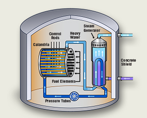
6. Areva (2016), “ATMEA1 Reactor: 1,100 MWe Pressurized Water Reactor”, http://www.areva.com/EN/global-offer-418/atmea1-a-pressurized-water-reactor-for-all-networks.html
7. ATMEA (2014), “Overview of the ATMEA1 Reactor”, http://www.atmea-sas.com/EN/home-330/atmea1-designed-according-to-the-highest-industry-standards-for-safety-performance-and-flexibility.html
8. ERIA (2015), “The Macroeconomic Impact of Coal-Fired Power Plants”, http://www.eria.org/RPR-FY2014-43.pdf
9. Viskovic and Franki (2015), “Coal Based Electricity Generation in South East Europe: A Case Study for Croatia”, International Journal of Energy Economics and Policy, Vol. 5, No. 1, 2015, pp. 206-230
10. Ye (2016), “Development features of supercritical (ultra-supercritical) technology in the world and experiences we can learn”, http://file.scirp.org/pdf/JPEE_2016061316361539.pdf
11. Rigzone (2016), “How Does Directional Drilling Work?”, http://www.rigzone.com/training/insight.asp?insight_id=295
12. US Department of Energy (2015), “Oil and Gas Technologies”, Chapter 7: Advancing Systems and Technologies to Produce Cleaner Fuels – Supplemental Information, http://energy.gov/sites/prod/files/2016/05/f32/Ch.7-SI-Oil-and-Gas-Technologies.pdf
13. ABB (2013), “Oil and gas production handbook: An introduction to oil and gas production, transport, refining and petrochemical industry”, https://library.e.abb.com/public/34d5b70e18f7d6c8c1257be500438ac3/Oil%20and%20gas%20production%20handbook%20ed3x0_web.pdf
14. European Commission (2011), “Smart Grid projects in Europe: lessons learned and current developments”, https://ses.jrc.ec.europa.eu/sites/ses/files/documents/smart_grid_projects_in_europe.pdf
15. IEA (2008), “World Energy Outlook 2008”, https://www.iea.org/media/weowebsite/2008-1994/WEO2008.pdf
16. Sheaffer, P. (2011), “Interconnection of Distributed Generation to Utility Systems, Recommendations for Technical Requirements, Procedures and Agreements, and Emerging Issues”, RAP, http://www.raponline.org/wp-content/uploads/2016/05/rap-sheaffer-interconnectionofdistributedgeneration-2011-09.pdf
17. Program Razvoja Pametnih Omrežij v Sloveniji (2012), http://www.giz-dee.si/Portals/0/Pametna%20omre%C5%BEja/Kljucni-dokumenti/Program%20razvoja%20PO%20v%20SLO.pdf
18. EDSO (2016), “European Distribution System Operators for Smart Grids”, http://www.edsoforsmartgrids.eu/wp-content/uploads/160129_Public-consultation-Energy-Efficiency-Review_final_EDSO.pdf
19. IEA (2011), “Technology Roadmap - Smart Grids”, https://www.iea.org/publications/freepublications/publication/smartgrids_roadmap.pdf
20. Smart Grids (2016), “National and Regional Smart Grids initiatives in Europe”, http://www.smartgrids.eu/documents/ETP%20SG%20National%20Platforms%20Catalogue%202016%20edition.pdf
21. Europagrid (2016), “HVDC Technology”, http://www.europagrid.com/hvdc-technology/
22. Prysmian Group (2015), “Low- and medium-voltage cables”, http://www.prysmiangroup.com/en/business_markets/markets/pd/products/medium-voltage/
23. Haegel, N., Margolis, R. et al. (2017), “Terawatt-scale photovoltaics: Trajectories and challenges”, Science, Vol. 356, Issue 6334, pp. 141-143
24. GEOFAR (2010), “Innovative Geothermal Applications”, Geothermal Finance and Awareness in European Regions, EU Funded Project
[1] One of the ETP Smart Grid’s goals is to offer strategic guidance for its stakeholders on the development of technologies related to smart grids that will address the future needs of electricity networks in the European electricity supply system (Smart Grids, 2016).
[2] Smart meters, a common form of smart grid technology, are digital meters that replace the old analog meters used in homes to record electrical usage. Digital meters can transmit energy consumption information back to the utility on a much more frequent schedule than analog meters, which require a meter reader to transmit information (US Department of Energy, 2014).